


Weeke "BHC 555 5/14" Optimat CNC Machining Center  Ended
Ended
Located in Western Wisconsin
- Winning Bid : $14,750.00 USD Sold
- 66 Bid(s)
- High Bidder: D****P
End of Year CNC Router Sale - Western Wisconsin ( Closed #13815492 )
Assets Include Weeke BHC 555 and Weeke BHC 650


-
Item Location
-
Make
WEEKE
-
Model
BHC 555 5/14 Optimat
-
Serial Number
0-250-17-0613
-
Year
2005
-
Phase
3 PHASE
-
Voltage
230/460
-
Inspection Date
-
Final Removal Date
-
Estimated Dimensions
-
Estimated Weight
-
Seller Comment
-
page views
3017
BHC-555 service records:
21 PMI service visits (preventive maintenance) basically two per year going back to 2005.
Replaced Z axis ballscrew in May 2007.
Repaired the front tool changer Oct. 2011
That’s it.
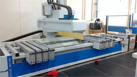
Weeke CNC Machining Center,
Model BHC 555 5/14 Optimat
Weeke's BHC 555 5/14 Optimat is a flexible CNC machining center designed primarily for routing, boring, and grooving of flat panel components without special workpiece fixtures.
The Weeke factory, located in Northern Germany, is uncompromising and maintains extremely high quality standards. They are an ISO 9001 certified machine tool builder. Weeke uses world class suppliers for critical items not made in house. Externally sourced components are sold and serviced on a worldwide basis and, of course, here in the U.S. Insistence on quality, coupled with the use of highly industrialized components, results in a very stable machining center--one that requires a minimum of inspection, preventive maintenance, or repair.
The BHC 555 5/14 Optimat is constructed on a steel frame, with heavy steel plates welded to the frame inside the base to insure stability. The design and substantial mass provide a solid, vibration-free platform for the machining head. The head rides on THK linear motion guides. In fact, the X-, Y-, and Z-axes are all supported on THK machine tool guides. THK guides were designed to produce extremely smooth positioning at high traverse rates. They have outstanding stability--both in the radial and side directions. The X-axis is driven by a zero-backlash, pre-loaded helically ground rack and pinion gear system. The Y- and Z-axes are driven by high precision ball screw.
Indramat solid state drives and digital AC servo motors are utilized to move the axes. Fiber-optic cables are used for communication between the drive system and the Beckhoff machine control.
The BHC 555 5/14 Optimat features a Windows based control with user-friendly WoodWOP 5.0 programming software. In addition to the programming software in the machine control, the WoodWOP program is included (on CD-ROM) for installation on other PC’s. With a PC in the office, the machine can be programmed off-line using the same intuitive icon driven software the operator has in the machine's computer control.
Machining Head Configuration
Weeke Unit #0023
Vertical Routing With Automatic Tool Changer (ATC)
A liquid cooled 9.0/12.0 kW vertical router motor with an automatic tool changer (ATC) is located on the right side of the spindle carriage. The spindle motor utilizes grease sealed ceramic bearings for higher performance and maximum bearing life. This spindle also uses the HSK63 standard for the taper in the spindle and the accompanying tool holders. The HSK63 design is the latest technology in tool holding systems and has been proven to be stiffer (less deflection) and much more accurate than conventional tapered shank designs, especially at high rpms. Additionally, the exceptional mass and rigidity of the machine's frame helps the router achieve a good surface finish with high feed rates and long tool life.
The router motor is equipped with two independent ride-along automatic tool/aggregate changers to perform tooling changes during program execution. This function can be a great advantage when different tool diameters and/or profiles are required to complete a given work piece. One magazine rides along on the backside of the spindle carriage and is protected against dust by a retracting door. This magazine is an 8-position unit and accepts both HSK tool holders and aggregates. The second magazine, also 8-position, rides along with the spindle carriage. This magazine accepts HSK tool holders but will not accept aggregates. With the two tool magazines combined, there is storage for up to 16 different routing tools available.
HSK toolholders are available in left or right rotation (CW or CCW), with a complete selection of collet sizes in inch or metric increments.
Vertical Boring with 25 High-Speed Spindles
The vertical-boring head is located at the back of the spindle carriage and has twenty-five (25) spindles. Fifteen (15) spindles aligned in the X-axis are typically utilized for row hole boring. Eight (8) spindles aligned in the Y-axis are typically utilized for construction hole boring. These spindles are on 32-mm center distances. Two (2) reinforced spindles, for large drills up to 35 mm in diameter, are offset from the in-line boring heads. The spindles are designed with a mechanical locking feature, which adds rigidity and stability (accuracy) to the drilling process.
Vertical Boring with 25 High-Speed Spindles (continued)
The vertical spindles are also equipped with a quick-change tooling feature for the drill bits. Standard drill bits equipped with a quick change pull-stud are easily inserted into the spindle and locked in place with this system. The drill spindles utilize standard boring bits, 70 mm long, up to 25 mm in diameter, with 10-mm diameter smooth shanks. The drill bits require a quick change pull-stud be installed at the end of the drill bit. A 2.7 kW motor drives the vertical-boring gearbox. Spindle rpm is programmable between 1,500 to 7,500 rpm.
Horizontal Boring with Six Individually Selectable Spindles
The horizontal-boring block has two (2) spindles oriented to the right, and two (2) to the left (X-axis), on 32-mm centers. There are also two (2) spindles in the Y-axis. One (1) spindle is oriented to the front, and one (1) spindle to the back of the machine. Spindle rpm is programmable between 1,500 to 7,500 rpm. Note: maximum horizontal boring depth is 45 mm.
Grooving Saw
The X-axis grooving saw is powered by the 2.7 kW, 60 Hz drill block motor. It is installed at the front of the machining head. 100-mm diameter saw blades are required for this unit. Spindle rpm is programmable between 2,000 to 7,500 rpm.
Rotary C-Axis
Weeke Unit #1067
The router motor is equipped with a full rotary C-axis. The axis is programmable from 0-360∞. C-axis orientation can be changed during the machining process. Orientation of aggregates is controlled by servo motor and is programmable from 0∞ to 360∞ around the Z-axis. An entire array of optional drilling, sawing, and routing aggregates are available and quoted under optional equipment.
Frequency Inverter
A solid state frequency inverter manufactured by KEB is utilized to power the router. The inverter output is programmable through the control with usable rpm range from 1,200 to 24,000 rpm. The design of the motor and frequency inverter provides constant power output between 9,000 to 18,000 rpm. Spindle rotation, RH or LH, is programmable.
Maximum Workpiece Thickness Limitations – Complete Processing
Maximum Workpiece Thickness Limitations – Routing Only
Panel Support Benches – Console Style
Weeke Unit #0108 and 0116
Eight (8) panel support benches have three (3) vacuum pods each. Two of the vacuum pods are 140 mm x 115 mm x 100 mm (height). The third vacuum pod is 75 mm x 125 mm x 100 mm (height). The support benches have a control button conveniently located on the front to disengage the pneumatic brakes for the X-axis adjustment of the bench. With eight (8) support benches, it is possible to load the machine with two (2) work pieces at a time.
Panel Feeding Rails
Panel feeding rails are supplied on six of the eight support benches. The rails are attached to one side of benches 1, 3, 4, 5, 6, and 8 (can be moved to either side). The rails move upward to provide a smooth surface for loading and unloading. The rails retract downward to set the panels on the vacuum pods.
LED Light System for Positioning Benches/Pods
An LED light system is used for quick and accurate positioning of the panel support benches and vacuum pods. The LED light system is positioned along the top of the machine base frame and along the sides of each support bench. LED’s are illuminated in the correct position for panel support benches and vacuum pods to be located, based on the CNC program for each part.
Part Positioning Stops
There are two sets of positioning stops on the machine. One set is located at the back of the machine and is used for positioning large parts. A second set of stops is located at the front of the support benches and is used for positioning narrow parts. Either set of stops can be used for positioning left-hand or right-hand parts.
Scrap Conveyor (4250 mm)
Weeke Unit #1812 and 1820
The scrap conveyor is installed in the base of the machine. Sawdust and small wood chips are transported to the left end of the machine and discharged approximately 10 to 12 inches above floor level.
Vacuum Pump
A powerful vacuum pump with 100 M/hr capacity has enough reserve suction for the most demanding jobs.
Dust Extraction Efficiency
Dust extraction efficiency is maximized by a central dust collection manifold, 250 mm in diameter, with individually controlled connections to the router, vertical boring block, and grooving saw. As each machining unit is activated, dust ports to other devices are automatically closed.
Perimeter Fence
A perimeter fence helps prevent accidental intrusion from the ends or back of the machine.
Safety Mats
Safety mats will assist in stopping the machine if the operator enters the working area while the machining head is in operation. The mats are divided into three (3) independent zones so you may load or unload parts at one end of the machine while the machine continues to work on the opposite end.
Weeke MCC Control
The machine is equipped with the Weeke MCC Control system featuring a Beckhoff PLC. MCC is a continuous path control system with intuitive programming software. The Weeke control features a graphic operator interface with icons to simplify operation. Programming with Windows based WoodWOP software is with simple coordinates or by the entry of formulas to define the relationship between panel size and machining locations (parametric programming). Some of the features of the Weeke MCC Control include the following:
- Personal Computer for operator interface
- PC is a Windows based Pentium compatible machine
- 20.0 GB hard drive
- 128 MB of RAM
- floppy disk drive 3.5"
- CD ROM drive
- the PC is connected to a Beckhoff programmable logic control for high speed, accurate, and reliable control of all machine functions
- high resolution color graphics with 15" TFT color monitor
- full function industrial keyboard
- bar code reader interface and software included (scanning device is optional)
- simultaneous three-axis linear control
- EtherNET interface for local area network (connection to office PCs)
- fully compatible and integrated with Holzma Cut-Rite Plus software
- report generation software included
- post processor for DXF file conversion is included
- RS-232 serial interface for simple PC connection
- Wood-Type font programming software included
Remote Diagnostics and Technical Support
Weeke Unit #8020
The MCC control is equipped with the hardware and software required for remote diagnostics and technical support. This system includes an on-board PC modem and remote service manager software. With this configuration, Stiles technical support can connect to the IPC control from a remote location to assist with troubleshooting and machine problem or error diagnosis. This service is provided with the machine free of charge for a period of two years from date of installation of the machine. Note: A dedicated phone line must be provided to the machine in order to use this feature. This is the customer’s responsibility.
Off-Line Programming
Weeke Unit #6060
In addition to the WoodWOP programming software in the machine control, this same software is included (on CD ROM) for installation on other PC’s. Using a PC in the office, the machine can be programmed off-line with the same intuitive icon driven WoodWOP software that the operator has within the machine control. The PC software has no copy protection. If you have a network, you may install the software on as many PCs as you like without buying additional copies of the software.
Simulation and Cycle Time Software
Weeke Unit #6101
The simulation software allows for graphic review of the machining process once a part has been programmed in WoodWOP. Additionally, the software calculates machine cycle times required to produce the part, based on the machine parameters. One copy of the software is pre-loaded on the machine. Additional copies of the software are available as optional equipment.
Off-Line Programming Training
Two seats in the Stiles Education course MC050 for training in the WoodWOP software are included with the machine. This course is designed to provide Weeke CNC Machining Center owners with the introductory information necessary to utilize WoodWOP software. Participants must have basic computer skills including use of Windows "operating systems".
Stiles Education classes are conducted at Stiles Machinery locations. The customer is responsible for all travel and living expenses incurred during training. Training scholarships will expire one (1) year from machine delivery. To enroll your employees, please contact Stiles Education at (616) 698-7500.
|
Number of vertical drilling spindles |
25 |
|
Vertical drilling spindle power |
2.7 kW/3.5 HP |
|
Vertical drilling spindle speed |
1,500 to 7,500 rpm |
|
Number of horizontal drilling spindles |
6 |
|
Horizontal drilling spindle power |
2.7 kW/3.5 HP |
|
Horizontal drilling spindle speed |
1,500 to 7,500 rpm |
|
X-axis grooving saw power |
2.7 kW/3.5 HP |
|
X-axis saw rotation speed |
2,000 to 7,500 rpm |
|
Saw blade diameter required |
100 mm/4” |
|
ATC router spindle power (power constant from 9000 rpm to 18000 rpm) |
9.0/12.0 kW; 12.0/16.0 HP |
|
ATC router spindle speed |
1,200 to 24,000 rpm |
|
Tool magazine capacity |
2 x 8 tools |
|
HSK63 tool holders supplied |
4 |
|
Collets for HSK63 tool holders |
4 |
|
Number of panel support benches |
8 |
|
Number of vacuum pods per bench/total |
3/24 |
|
Number of panel feeding rails |
6 |
|
Vacuum pump capacity |
100 M/hr |
|
Length of machine |
7580 mm/24’ 10” |
|
Width of machine |
4650 mm/15’ 3” |
|
Height of machine |
2820 mm/111” |
|
Working length |
4250 mm/167” |
|
Working width - support bench width |
1500 mm/59” |
|
Max. panel thickness |
125 mm/4.9” |
|
Machine weight |
6200 kg/13,700 lbs. |
|
Max. drilling depth for through holes |
55 mm |
|
Axis stroke/positioning speed |
|
|
X-axis |
5050 mm/80 M/min |
|
Y-axis |
2150 mm/60 M/min |
|
Z-axis |
370 mm/20 M/min |
|
C-axis |
0-360∞ |
Utility Requirements
|
Electrical |
||
|
Operating Voltage |
230/460 Volts / 3 Phase / 50/60 Hz |
|
|
Amperage Service |
80/50 Amps @ 230/460 Volts |
|
|
Control Voltage |
24 Volt |
|
|
Total Connected Load |
22 kW |
|
|
Dust Extraction |
||
|
Connection Size(s) |
250 mm |
|
|
Air Velocity (minimum) |
28 m/sec |
92 ft/sec |
|
Static Pressure |
Minimum 2200 PA |
|
|
Air Volume |
4950 m/h |
2915 cfm |
|
Compressed Air |
||
|
Connection Size(s) |
½ in |
|
|
Pressure Required |
100 psi |
7 bar |
|
Consumption / Volume |
300-500 l/min |
11-18 cfm |
|
Ambient Temperature |
||
|
Operating Range |
10∞ - 40∞ C (min/max) |
50∞ - 100∞ F (min/max) |
|
Foundation Requirement |
||
|
Concrete Thickness |
200 mm (min.) |
8 in (min.) |
Voltage supplied must not fluctuate in excess of =/- 5 % of its stated value. Voltage must be balanced phase-to-phase and phase-to-ground.
Note: The stated values are only applicable to the machine as specified. Adding or deleting optional equipment may change service connection requirements.
The listed specifications & information were taken from the manufacturer’s published information, internet research, or seller’s description.
The specifications & information are assumed to be correct; however, in no way, guaranteed. Bidders are encouraged to inspect the machine, call with questions, or contact the manufacturer for more information.
Please log in to view the bid history
LoginNo information available